
Plurality, an unsolved UI problem.
January 31, 2018
Another user-interface post. At this rate, we’ll have sorted this out by 4082 a.d.
Ran into a problem today and I have _no_ idea on how to continue. Well, a few ideas, but they’re all terrible. I’m just going to ramble on about this hoping it’ll nudge my brain, but do not expect graphics or even halfway decent prose. I’m desperate, and in a hurry.
Most controls (textboxes, checkedboxes, radiobuttons, sliders, colour fields, …) are there to inform about and provide a means to change the state of the computer. Exceptions are passive controls such as labels or graphs that are merely there to inform, and controls which only do things, without showing information. Sometimes buttons fall in this latter category, but even buttons can have different text depending on state or may be disabled when it makes no sense to push them.
Let’s focus on three common controls for the time being; checkboxes, textboxes, and (number)sliders. It is easy to see how these all work pretty well considering their ultimate purpose. They allow the user to both see and change a boolean, a string, or a number state respectively. If the state is YES, then the checkbox will contain a check, clicking on it will remove the check mark and switch the state to NO.
But it is possible for the state itself to exist in more than one state. Either there is a single state (great, we know how to deal with that), there is no current state (this could be a problem), or there is a plurality of different states (we’re hosed). This is easy to see if we imagine our controls to represent some properties of a geometric curve in a graphics application. For example the checkbox could be bound to the curve’s printable state (YES=include when printed, NO=omit from printed output), the textbox bound to the object’s name, and the slider bound to the line-width of the curve. When a single curve is selected these controls will work perfectly well, but when no curve is selected there is no underlying state.
In this case the checkbox cannot be empty, because that implies an off-state, the textbox cannot be empty because that implies no-name, and every single slider design I have ever seen certainly doesn’t support an empty mode. So what do we normally do? We disable the controls, making them all look faded or sunken or transparent. It’s a kind of solution that kind of works well enough. The appearance of the control is significantly different from the enabled mode that we can tell the difference between a checkbox that is YES, NO or DISABLED.
But the real problems start when we select more than one curve. Now potentially we have a checkbox, a textbox and a slider that are associated with multiple, different states. The existing solutions to this problem are inconsistent and bad. Let’s begin with the least bad and least inconsistent one; the checkbox.
I think all decent UI platforms provide checkboxes that have an ‘indeterminate’ state. A quick Google Image search immediately yields plenty of examples. This is how Microsoft decided to solve the plurality problem for checkboxes:
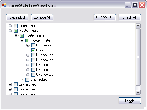
On, Off, and Indeterminate states of standard Windows checkbox controls.
So what’s bad about it? Well, first of all the INTERMEDIATE state is more prominent than the ON state, filling more pixels with the same green. This makes it seem more certain of itself rather than less. Secondly, plenty of people colour in entire squares when filling out forms, so the fact that we agreed that a check-mark signifies ON while a square signifies INDETERMINATE is an ad hoc decision that will not be obvious until after someone explains it to you. Thirdly, it tells you nothing about the imbalance of the plurality. Does this one ambiguous checkbox represent 50 YES and 50 NO values, or 99 YES and only one NO value? This is important information because a reasonably balanced ambiguity tells us it’s probably fine, whereas a heavily imbalanced ambiguity tells us that a few values are probably wrong. Lastly —and for the checkbox not particularly important— there is no way to go from UNDETERMINED to a specific state. When we click on an undetermined checkbox it will either turn YES or NO, either based on OS or App logic. The user doesn’t get to pick. Now as I said, for checkboxes that’s not that big a deal because the other option is only one more click away, but keep an eye on this.
What about textboxes? Here too there is a commonly accepted solution. If a textbox is supposed to display more than one string, the program will helpfully render the string “<varies>” instead. This is somewhat informative but exceedingly unhelpful. Again it doesn’t tell us anything about the balance, and it obscures all the actual data. There is no mechanism for us to pick one of the available strings and assign it to all states. It also doesn’t tell us whether we are dealing with two, three, four or fifty thousand different strings. Or for each string how often it occurs amongst the conflicting states. Or what the commonalities are between all the different strings, for example do they all start with “city:”?
I can see a solution to this, but it only really works in the case of a small amount of conflicting states. Instead of “<varies>”, the textbox could show “city:London city:Paris city:Berlin“, with each unit being clickable. They can be sorted from most-common to least-common, or some other order if that makes more sense. But this clearly doesn’t scale to a large amount of conflicting states, and also easily requires more screen space than the original textbox.
The case is maximally bad for number sliders. There are no common solutions, or even uncommon ones (if you know one tell me!). Most slider controls do not allow you to hide the grip, but even if they did where would you click to set a new value for all states? My imperfect solution would be to draw various grips, all very faded or transparent, and allow the user to click on one to copy a specific state to the entire set. But again doesn’t work if there are loads of different states, or if two states are very close together making it impossible to reliably pick one over the other. Maybe it makes more sense to show a statistical distribution instead of grips? I do not know.
Sliders, an unsolved UI problem.
November 28, 2016
Everybody loves sliders, and for good reasons. They are easy to understand, they provide useful hints regarding sensible ranges for values, they can display values both numerically and spatially at the same time, and —provided they are wide enough— allow one to change a value both slightly and drastically with the same amount of effort.
Text fields where numbers must be entered using the keyboard, up-down controls where every change requires a click, and dropdown lists where values can be selected from a finite set are far more cumbersome to use. I suspect the only reason we still see them a lot is because they each do one specific thing better than a slider. To wit, sliders have problems with:
- Incrementing/decrementing values by the smallest possible amount.
- Setting very specific values.
- Selecting values from a non-equally spaced set.
- Selecting values without lower and upper limits.
Today I decided that it was time to start work on the core slider class in Grasshopper 2.0, which is going to be a rather ubiquitous interface element, as indeed it is in the current version, so I need to get this right.
I’m not going to wax on about implementation, or show off any solutions yet (it has only been a day, the GH2 sliders are barely functional), but here is a list of problems I expect good slider design to solve.
- It must be easy to set a specific value. This problem has been solved in GH1 already, just start typing whenever a slider is selected (or double click a slider if you’re on the canvas) and it is replaced by a text field into which an exact value can be typed.
The only improvement upon this I can think of is the ability to use voice recognition or stylus OCR to set the value. - It must be easy to move a slider to the next or previous allowed value. A slider has a fixed number of decimals, and it is entirely possible that the distance between 0.506 and 0.507 is less than one pixel. Possible solutions include zooming in (not always possible, depends on the UI context in which the slider appears), using arrow keys to nudge the slider left and right, or —again— voice/gestures. A more traditional approach may be to remap the mouse coordinates so that a one pixel motion translates to exactly one epsilon.
- It must be possible to have preset values along the slider domain that can be snapped to. These presets must support custom names, so that a slider can be dragged from left to right while displaying {…, 0.48, 0.49, half, 0.51, 0.52, …} where “half” would be a named preset.
- When dragging a slider across a preset value, it must always come to rest at it, so even when there are multiple presets very close together, dragging the slider grip across them must result in each one being visited. This is turning out to be a lot harder than it sounds.
- Sliders that use small grips without numeric display, must still display the numeric values during dragging, and possibly on mouse-hover.
- Slider grips must come in various shapes; small without numeric value, box containing numeric value, bar containing numeric value. Furthermore various positions of the box and bar will result in numeric values that do not take up the same amount of horizontal pixels. Specifically when minus signs or preset names are involved, or when using a font which does not have tabular digits, ie. 11.1 is a lot narrower than 88.8.
While dragging, the width of the grip must never change so it must be big enough to contain the widest possible value. - When two or more sliders are stacked vertically, the width of their grips must be identical, or it just looks plain ugly. So it must be possible to bundle sliders together into aggregates and have them be aware of each other’s dimensions.
- Sliders should have a uniform appearance across the UI, but it must be possible to override specific visual properties, such as fill, background, or font without having to then do all the drawing in a custom function.
- Value change events need to be specific about whether the change is intermediate or final. If a slider value change is going to kick off a lengthy calculation, developers listening to the slider may want to ignore intermediate events that would occur during slider drags.
- The user must be able to drag a slider without it broadcasting events all over the place, for example by holding down the alt-key while dragging. Such a ‘silent’ drag must be visually distinct from a ‘loud’ drag.
- It must be easy for the developer to provide a bunch of meaningful defaults for a slider, and to offer undo/redo support.
The UI kits I’ve worked with in the past written by others meet 3, maybe 4 of these demands. I have yet to see software which treats sliders with the respect and gravity they demand, how is it that something as fundamental as this is still not working as it should in 20 fucking 16?
Drawing Graphs in GH2
November 29, 2015
One of the more conspicuous ways in which working in Grasshopper differs from working in -say- Visual Studio, is that it is trivial to tweak values by hand at runtime. If one wishes to provide control over some constant used in a C# algorithm, one must either build a UI with buttons, sliders, checkboxes and whatnot, or maintain a live link to a settings file which can then be modified using notepad. The first approach requires a fair amount of work on the part of the developer, the latter is supremely user-unfriendly.

Although we collect no data on this, I would not be surprised in the least to find out that the most commonly used object in all Grasshopper files ever is the number slider. Numbers are almost always one of the required inputs of any given algorithm, and the slider provides an easy way to interactively adjust them. I do not think the implementation of sliders in Grasshopper 1.0 is perfect, but at least access to numeric constants works far better than the way in which GH1 provides access to equations. The Graph Mapper object is probably the most commonly used worst piece of UI garbage in the history of Grasshopper.

Science!
Fabricator font update
March 24, 2015
First beta of the fabricator font code library and plug-in have been released, see discourse topic for download links to documentation and binaries.
In this post I shall explain how to add custom symbols to a fab font and how to invoke them inside text.
Step 1. Open the font you wish to extend. It’s also possible to create a new font with only the custom graphics and merge it with a pre-existing font manually, but in this post we’ll work with font source geometry.
The AtoB default font that ships with the fabricator font library.
Step 2. Decide where to put the new graphics. Every symbol has to be entirely within a unicode character cell. We’ll pick ‘L’ because we’re going to add logo graphics.
The upper-case L unicode cell.
Step 3. Add a new layer to the 3dm file whose name matches the style name of the graphics you wish to add. You can pick whatever name you want, as long as it consists of only alphanumeric characters. In this case, the new style is called ‘Logo’.
A new layer represents a new style.
Step 4. Draw the new graphics into the ‘L’ cell on the correct layer. The original L geometry has been hidden, but is still part of the ‘Default’ layer. I’ve shamelessly ripped off the old Buro Happold logo, just because I like it, it’s easy to draw and it consists of only lines. Note that only Lines, Circles and Arcs can be used as symbol geometry.
New geometry inside the ‘L’ cell, on the ‘Logo’ layer.
Step 5. Publish the new extended font. The style name ‘Logo’ now appears in the publishing messages.
Publishing messages.
Step 6. Once you have an extended font, you’ll have to specifically import it during the FontMakeText command, otherwise the default font is used. You’ll also have to add a mapping that converts all occurrences of the string “<logo>” with the string “L” in the Logo style.
Custom symbols in an extended font can be accessed with a custom mapping.
Further forays, fresh flaws for fabricator fonts
October 4, 2014
Some headway to report on the geometric font project. There was an early comment by Willem Derks regarding the need to have control over stencilling. After all the focus of this project is manufacturing, meaning that we do expect people to actually cut holes into sheet material based on our strokes. Without stencilling we can end up with topologically disjoint remains (for example the insides of ‘o’, ‘8’ and ‘g’). However we decided it’s not good enough to supply a secondary typeface which has stencil gaps, as the radius of the gaps very much depends on the size of the cutter, the thickness and even the strength of the material.

Stencil bridges to avoid disjoint remains.
On the left you can see the formation of islands when symbol strokes form a closed loop. Adding a single bridge will connect the inside of the g with the rest of the material, but it could be a very weak connection as the bending moment across the bridge can be large if the island is long. If the sheet material is strong though this is not a problem. This is why we decided to cater for both primary and secondary bridges. The font designer merely has to put points on the symbol geometry to specify where primary and secondary bridges can be made and the end-user can specify what radii to assign to each category:

Some text without any bridges. This will work fine if the text is burned or milled onto the material without cutting all the way through.

The same text with only primary stencil bridges. Strong material like thick metal sheeting should be able to handle these connections. Of course the user can specify larger bridge widths depending on the milling radius.

Both primary and secondary stencil bridges are now made. There could still be a large bending moment if the ‘islands’ have a large maximum distance to the axis between two stencil bridges.
Although stencilling is finished enough for an initial beta release, there are still problems with the kerning engine. On the whole it works reasonably well and there’s plenty of settings to control the distance between adjacent characters:

Some settings for the layout/kerning engine. Click to embiggen.
Characters can be positioned at fixed intervals (mono-spacing), based on their bounding boxes or based on their actual shapes. The kerning distance between two adjacent symbols is computed iteratively to a high degree of accuracy (which doesn’t usually take more than 3 or 4 iterations). Note that characters consist both of visible and invisible geometry.
I did find that positioning symbols based on a fixed minimum distance did not always visually please. As a result I decided to add a friction curve to the kerning engine. Friction retards the intrusion of one symbol into the bounding box of another. For example two adjacent symbols can be positioned very much ‘inside each other’:

Kerning may push a symbol so far leftwards that its bounding box intersect with the box of the previous symbol. In rare cases a symbol may even be placed entirely within the previous symbols’s bounding box. For example the combination ‘C-‘ could result in very strong kerning.
A kerning friction curve lessens motion due to kerning by simulating increasing friction. The further one bounding box is pushed into another, the harder it gets to push it further. I provided both linear and non-linear friction curves, mostly because I have no idea yet what works well.
The last serious (known) bug to solve is to do with intersecting symbols. The example above shows that the text ‘3,4’ results in intersecting symbols as the comma is kerned underneath the ‘3’ and the ‘4’ is kerned over the comma. Kerning is at present purely a two symbol algorithm, which is clearly insufficient. I’ll either have to maintain a spacing front which moves from left to right as individual symbols are positioned, or I simply need to take all existing symbols into account when positioning the next one.
I can certainly see why professional typefaces often come with manually designed kerning offsets…
Oh and of course there’s now also proper file icons for fonts and symbols:

*.font files are just zip archives containing any amount of *.symbol files. Makes sharing easier without closing the format.
Immutable classes, my new favourite methodology
September 8, 2014
As part of Grasshopper 2.0 development I’m trying to read up on good and modern coding practices. Since multi-threading is a design goal for GH2, I need to make sure that the foundations of the new code are thread-safe. There’s more than one way to make code thread-safe of course, but I’ve become exceedingly fond of the immutable types approach. It helps that Eric Lippert is advocating immutability, he typically knows what he’s on about.
There are more than one ways to think about immutability, but here I’m concerned with write-once immutability, meaning that fields get assigned from within constructors and then are never allowed to be replaced with another value. The problem is that C# has no fundamental game plan when it comes to immutability and thus trying to use the concept in your own code means treading very, very carefully.
Fonts for manufacturing processes
September 2, 2014
Fonts are great. Seriously. They occupy precious real-estate on that narrow overlap between the magistera of Art and Geekdom. Most fonts are defined as closed outlines, the interior of which is what you see. It’s this interior which gets assigned different pixel values on screens or which gets filled with ink on paper. By and large this works really well. The outline approach gives font designers full control over every single geometric aspect of their creations, thus making it possible to design fonts that are a pleasure to read.

But not all text is meant for leisurely consumption, quite often text is engraved or printed onto objects merely as an identifier; ‘Part #576’, ‘Assembly A2’, ‘This side up’. Especially with the advent of computational/algorithmic design and programmable manufacturing, it’s not uncommon to have an assembly featuring hundreds or even thousands of slightly different shapes, which have to be screwed together in the right order. In this case you probably want to include some sort of identifier on each part, and you’ll want to add them without the intervention of a human being who will undoubtedly c*ck it up. Regular fonts that were designed to define the outlines of symbols are not ideal if you’re using a milling machine or a laser cutter to engrave them.

The total length of all symbol outlines is nearly 590 units. Thus the ratio of horizontal text length to text outline length is almost 1:6. Not only is a font like Times New Roman difficult to read when rendered as outlines instead of fills, it also takes a long time to steer the laser or milling bit over all the curves.
There do of course exist single line fonts that describe their geometry in terms of central splines instead of outlines. A quick Google image search yields a large number of potentially halfway decent fonts.

So why don’t we just install one or more of these and select them as the font of choice when generating tags for automated manufacturing? Well, the answer of course is that we do, because it is the single best option available at the moment. But this solutions suffers from and even causes new problems. First of all, fonts were not meant to be single lines, and installing such fonts as system resources may confuse (and sometimes even crash) other programs that attempt to interpret them as outline fonts. Since single-line fonts have a very narrow purpose, it seems like overkill to install them at the OS level. Secondly these fonts often lack characters such as Æ, Ñ, ð, Þ and ß, which may be non-standard in English but are nevertheless commonplace in Iceland, Germany, Turkey, Greece, Russia, France, Estonia, Denmark, Albania, Hungary, Romania, Spain, … enfin, you get the point. Lastly, this geometry is still stored inside TrueType or OpenType font formats, which makes them hard to get at. It’s difficult for programmers to access the clean geometry without referencing 3rd party dlls, and it’s difficult for users to modify or extend a font. First you need to find a font editor that is affordable and modern enough. Then you need to get accustomed to a workflow which can most likely be picked on a scale somewhere between arcane and atrocious.
So in this light I’d like to propose an alternative. I’m not a professional typographer so I may well be underestimating the difficulty of the task ahead, but on the other hand all the worlds professional typographers haven’t managed to solve my problems after trying really hard for 50 years so I’m not convinced we should be listening to them. Instead of making yet another single line font, or writing some software which is really good at interpreting existing single-line font definitions, let us take a step back and re-evaluate what sort of solution would actually solve the problem.
We need to:
- etch, burn, mill or engrave small amounts of symbols onto a wide range of materials which come in a wide range of shapes,
- automatically generate and place these symbols using algorithms.
We’d like to:
- have a good grasp on the geometry of the symbols,
- be able to modify, extend or replace the pool of symbols ourselves, using graphics software we know well,
- not spend too much time etching the symbols, time is money.
We don’t care about:
- performance much. We’re not typesetting books here, just putting a few scratches on a piece of wood.
- Pleasingness to the eye. Fine-tuned kerning, ligatures, good italic and bold styles are not sought after properties.
It is reasonably easy to use Rhino (or any other drafting software you may be familiar with) to design a single line font. The plethora of drawing tools Rhino provides (snaps, accurate transformations, measuring tools, etc) make the design portion of the problem very tractable. But where to go from here? How does one convert hand-drawn curves into a usable font? I spend the last two days writing a small plugin for Rhino which consumes curves and points (more on points later) and generates very easy to access font data from them. Instead of putting the entire font into a single file, I decided to store each character in its own textfile:

The name of the folder which contains them all equals the font name, and each filename represents the unicode identifier of the character in question. Hashes can be used for comments and in the example above the first two lines are auto-generated comments. The body of the file contains one Codepoint line which identifies the file content. It should be the same as the file name. The geometry of the symbol is a collection of lines, circles and arcs (no bezier/nurbs curves allowed yet), each represented by a sequence of numbers, [center.x, center.y, radius] for circles, [start.x, start.y, end.x, end.y] for lines and [start.x, start.y, end.x, end.y, tangent.x, tangent.y] for arcs.
To ease the process of writing these files, the plugin I’m working on overlays a bunch of unicode pages onto the Rhino model space, so all you have to do is make sure your curves are inside the correct square:

Any lines, arcs, circles and points found inside the appropriate square will automatically be combined into a single symbol file. Each symbol cell shows common font metrics (adjustable using commands) as well as a character preview and the unicode codepoint. Since the unicode space is huge, I also draw a small grid inside each cell as the Rhino grid tends to peter out pretty quick once you’re away from the origin:

The above image shows not just the symbol cells, but also the font preview. After exporting the Rhino curves to a collection of *.char files, those files can be read back in and displayed in the correct cells. This makes it easy to visually check the correctness of the symbol files. Different types of symbol fragments are drawn in different colours (lines in magenta, arcs in red, circles in orange and points in teal).
Incidentally this font definition does not (yet) allow for customized kerning offsets, so the plan is to write an automatic kerning engine for the font interpreter. This work hasn’t been done yet but since I’m not aiming to write the worlds best kerning algorithm it shouldn’t be too difficult. The aforementioned point geometry which can be part of symbol files is never included as part of the visible font, but it allows the designer to increase the ‘size’ of the symbol visible to the kerning engine.
This project is only two days old at this point in time and there’s a lot of work left to do, most notably combining the symbols to make actual text. You can see a YouTube video of what’s working so far here:
ICGG2014 paper
August 22, 2014
The 16th International Conference on Geometry and Graphics has come and gone. I had a lot of fun, it was certainly very different from the usual software gigs I attend. This was a congregation of mathematicians and educators from all over the world (though mostly Central and Eastern Europe and the Far East) where most attendees were also presenting a paper or poster. The conferences I usually attend have at least a 1:20 ratio of speakers to audience. That hierarchy was entirely absent at ICGG, which was probably at least in part responsible for extreme levels of conviviality. At the conference dinner a lot of national groups sang songs from the homeland, and we even had the pleasure of hearing the Russian and Ukrainian delegates perform Moscow Nights together.
As promised and agreed with the conference organisers, I’m now making my paper available for download here. The paper is much more technical than the plenary lecture, dealing with the mathematical and algorithmic characteristics of generic solvers and fitness landscapes. During the talk I focused mostly on the graphical aspect of landscapes and how specific problem definitions result in specific landscape geometries/topologies. The Prezi for the lecture is of course also available, as are the files I used for the live demonstrations.
Illustrations for my ICGG2014 paper
February 17, 2014
I’ve written a paper for the ICGG2014 conference to go with my talk. It mostly talks about the theoretical side of things, whereas the talk is going to focus on the pragmatic. In case they won’t accept it I’ll post it here soon, but if they do then it will be available online sometime after the conference.
Over the past few years I’ve grown increasingly tired of slick computer generated graphics. They all too often fail to draw attention to salient details and convey meaning. It’s rare these days that I get to make large illustrations, most of my graphic work is for icons, so I do try and savour it when I get the chance. I’ve put the 10 images I drew for this publication below the fold (with LaTeX overlays and captions).
My first LaTeX document
February 6, 2014
Donald Knuth is one of the people who got a Grasshopper banner animation (january 10th), but until last week I’d never seriously looked into(La)TeX, probably his most famous contribution to humanity. I’ve been invited to give a lecture at ICGG2014 come August and the abstracts and papers are to be submitted in either tex or doc format. Since I don’t own and can’t stand Word® and pretty much every other word processing software I’ve ever seen*, it seemed like a good opportunity to dive into TeX. It’s a curious mixture of pure awesomeness and horrific muck. One the one hand it’s extremely liberating to be able to program a document rather than write one. It seems that no matter what you want to do, there’s always a way to get there. I’m also very pleased about being able to write in pure text and compiling the final document, as opposed to trying to tell a GUI what it is I want and never quite knowing what monstrously nested makeup and layout tags are silently ganging up on me in the background.
But the implementations of TeX seem to suffer badly from softwareforprogrammersitis. TexWorks (which comes installed with MikTex for Windows) was clearly made by someone who has heard about that thing called UX but wants no truck with it. Once I have some time to do some more research I’ll definitely be looking at a lot of alternative editors, but the dozen or so I’ve seen so far do not fill me with hope. With a bit of luck the LaTeX for Sublime Text will work better.
Anyone has any suggestions?
* TechWriter for RiscOs was ok, but I no longer own an Acorn machine and this was 20 years ago.
